

There is so much that can be done in CAD compared to hand drafted drawings, except the character that comes only in hand drawings. CAD due to its layers feature and attributes of the layers makes it possible to “filter” several drawings out of a single drawing (2D or 3D). This post informs of what and how layers can be used powerfully, especially CAD layers for Indian Temples and Heritage structures.

CAD and Layers – the beginning
CAD originally started as a replacement to traditional architectural drawings with additional advantages, like quick updates and corrections. It always had the layers feature to have objects (lines and shapes of the drawing) belong to a particular layer. Each layer had properties like color and line type and thickness, and more essentially “visibility”. This enabled to change properties in one go for all lines or all dotted lines or change dotted line to a thin line or to even hide some type of lines. This was so far so good. From this early start it went on to use layers for specific agencies and categories – lighting, plumbing, electrification etc. Layering conventions developed and were published for the industry. So far I have not come across a standard layering convention followed between all agencies. In practice, drawings continue to use free style naming and grouping. Each office attempts its own layering convention to bring some order in the chaos, and things somehow get managed! Who in running practice can manage to follow something defined as this example of a convention?
CAD Layers for Heritage Structures
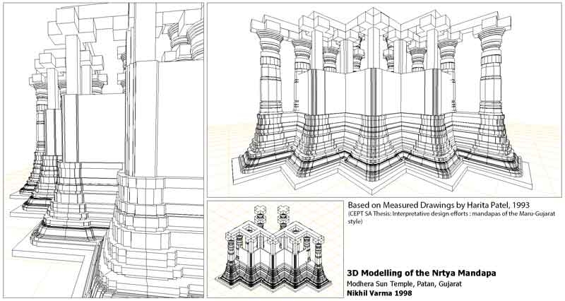
But research of heritage structures, especially structures like the Indian Temple, requires a methodical approach. Need to utilise CAD, much more than a mere digital drawing tool. Structured Layers can enable far richer drawings by sensitively choosing line qualities that are configured for each scale the drawing is printed to – something the default line type has killed in CAD drawings (how CAD killed character in drawings requires a separate post, I may write someday). We started developing our own layering convention in 1998 for Indian Temple architecture and Indian Heritage structures in general. The naming convention is designed to allow several versions out of the same drawing instead of creating newer drawing for each type of application. The same is applicable for objects in a 3D model, and allow several types of views as needed.
For example, a 3D model can be seen just till plinth level or till wall level, by hiding pre-defined layer groups. The same layering method is applied in an apparent complicated use. Most people may prefer to create different models/drawings for this purpose, when it can be done smartly in a more structurally appropriate manner. The complication of using 1.properties of an object + 2.properties of a layer + 3.properties of a block (=group of objects) can yield amazing views out of the same model. This structured use of layers already informs the structural construction of the real architecture. Combination of 1+2+3 above, can create a view that is just till plinth level, till middle of wall (including portions of a column), without columns, without walls… In a linear way this can be achieved by duplication of layers and selectively hiding them. The convention we have developed makes this much more structurally intuitive and easy by using naming conventions, selection-sets based of the naming convention (wild card characters) and guiding block creation in this manner. If you are interested to know more write to us.
Example | Map of Kavaledurga
Map of Kavaledurga with separate layers and layer groups for Objects (water bodies, ramparts, gates and artefacts), Regions and Contour data. The layers are selectively utilised for the use and application of the map.

Example | A temple complex in Siddhpur, Gujarat
The following drawing is a part of a study of a temple complex in Siddhpur, Gujarat. The grid of drawings is based on the same drawing using different visibility of layers for each cell. The study comprised expression of experiential qualities of a temple complex as one approaches it – transition from the externally visible super structures to eventual internal space of the temple complex. CAD Layers were structured to create concurrent drawings, out of the same 2D drawing and 3D model. Layers are called the same in each cell, making it possible to immediately express the same concept (=selection of layers) in various modes.


